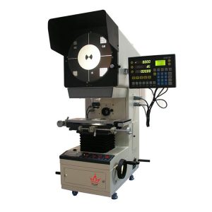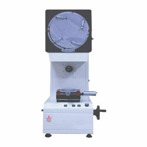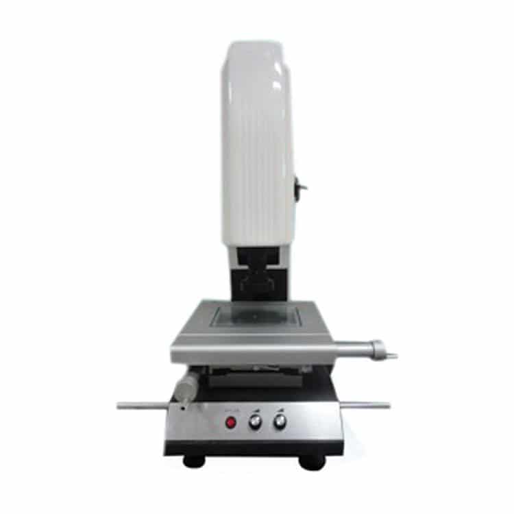
Optical Image Measuring Instrument
Optical Image Measuring Instrument is widely used in all fields of application with two coordinates for the purpose, such as machinery, electronics, instruments, and plastic, etc.
| Accuracy | (3+L/75)µm L: length of the tester, units: mm |
|---|---|
| Temporal resolution | 0.001mm |
| Repeatable accuracy | 0.002mm |
| Eyepiece | 0.5X (Optional: 1X, 2X) |
| Objective | 0.7X-4.5X |
| Magnification | 20X-120X |
Details About Optical Image Measuring Instrument
Features:
- Varifocus objective and graticule marker generator as the measurement aiming system.
- Various data processing and display, input and output functions, especially the function of adjusting sample is very useful.
- High resolution and set times for the objective, to change the rate doesn’t need to rechoose the scale.
- Spare R232 interface, the specialized software can deal with and output the surveying and mapping graphics after conecting with computer.
Standard Function:
- Can take pictures of the products, and store in the computer to form a product atlas as the form of jpeg.
- Compare the photos stored in the computer with the Real-time images in the same screen.
- The pictures can be input to AutoCAD to become an engineering drawing.
- AutoCAD standard engineering drawings can be input into real-time image, making AutoCAD engineering drawings and the actual shape overlap, then compare them, as to find out their difference.
- Can input previously stored jpeg image to the real-time image.
- Can dimensioning in bird’s eye view of the map.
- Customer-defined circle: make a standard circle according to clients’ needs, and then compare the standard circle with the actual sample overlapped, so as to find the error between them.
- Customer-defined segment: can define the starting point coordinates, length, and rotating angle of the segment, and then compare with the actual sample overlapped, so as to find the error between them.
- Customer-defined coordinate: define the Coordinates origin as (0, 0) in the Actual sample of the real-time image, then Mark any point of the picture’s coordinate position.
- Dim ordinate: To make the self-defined origin (0, 0) as a benchmark, and then mark any point of the picture’s coordinate position.
- Patent taking R Angle function: accurate plane taking R Angle mode in the present market condition.
- Measurement: can measure any physical dimension in the plane. (Angle, diameter, radius, distance of point to the line, two round eccentric, and distance between two points)
- Plotting: can describe the shape of the actual sample in the Real-time image, and then form a complete engineering drawing. (Drawing mode is similar to AutoCAD)
- Mark: Can mark any physical dimension in real-time image. (Length, angle, diameter, radius, distance of point to the line, and distance between two points)
Technical parameters:
| Type | 1510 Manual | 2010 Manual | 3020 Manual | 4030 Manual |
| Dimension (mm) | 600*500*850 | 600*500*850 | 850*600*900 | 970*670*940 |
| Metal table dimension (mm) | 345*250 | 345*250 | 450*350 | 650*350 |
| Glass table dimension (mm) | 220*150 | 220*150 | 340*240 | 480*370 |
| Actual working stroke (mm) | 150*100*120 | 200*100*130 | 300*200*150 | 400*300*150 |
| Weight (KG) | 100 | 110 | 200 | 250 |
- Cabinet base: Granite: Level 00 Granite
- Accuracy: (3+L/75)µm L: length of the tester, units: mm
- Surface lighting: LED annulus super bright UHP (brightness is adjustable)
- Silhouette lighting: LED super bright circular lamp (brightness is adjustable)
- Calculation and measurement: REICA 2.5D Precise-measurement software
- Temporal resolution: 0.001mm
- Repeatable accuracy: 0.002mm
- CCD: SONY chip, 1/3 colorful CCD
- Eyepiece: 0.5X (Optional: 1X, 2X)
- Objective: 0.7X-4.5X, Magnification: 20X-120X
- Power supplier: AC90-264V, 50/60Hz
- Carrying capacity: 30KG
- Operation mode: By hand (Micro adjustment and quick movement)
Share Optical Image Measuring Instrument With Others
Share to Facebook
Share to Twitter
Share to LinkedIn
Share to Pinterest