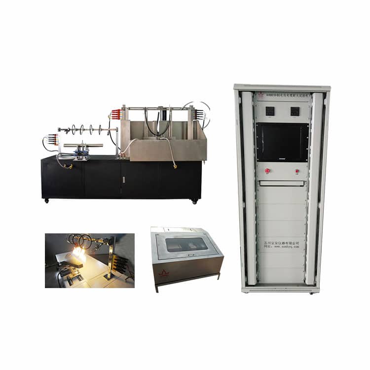

BS Wire and Cable Fire Resistance Tester AH68018-A
BS Wire and Cable Fire Resistance Tester is suitable for fire resistance test, water spray fire resistance test and mechanical fire resistance test. It is suitable for mineral insulated cable with rated voltage not exceeding 450/750V. It keeps the circuit intact for a long time under flame conditions. It complies with British Fireproof Cable Standard BS6387 “Guidelines for Maintaining Circuit Performance of Cables in Case of Fire”. The test machine simultaneously meets the BS8491 standard for assessing fire integrity of large diameter cables as a component using the smoke and heat control system given BS7346-6, and identifying other activities of the fire safety system. It is suitable for cables with a cable rated voltage not exceeding 600/1 000 V and an outer diameter greater than 20 mm.
Details About BS Wire and Cable Fire Resistance Tester AH68018-A
Standard:
BS6387 2013
BS8491: 2008
GB/T19216
Technical parameters
Fire resistance Test, Includes below:
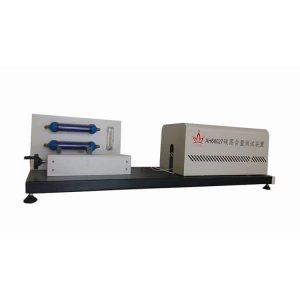
- Cable supporting system: Use clip to horizontally clip cable’s sheath. Middle of the cable is fixed by two metal rings (distance of 300mm). ATTENTION: Metal rings and other metal parts should be earthing. For non-armoured cable whose diameter is under 10mm, or some other cables which will happen obvious displacement, should be fixed by 3 metal rings. Each metal ring should be fixed in the original one at a distance of 150 mm.
- Continuous detection device: Let current go through all the cores of cable when in test, a three-phase star-shaped connected transformer or three single phase transformers (or one single phase transformer, if test sample is single core cable.), and has enough ability to keep max allowable leakage current of 3A under test voltage. Each core of cable in the other end connects with a lamp, and load current of 0.25A under rated voltage.
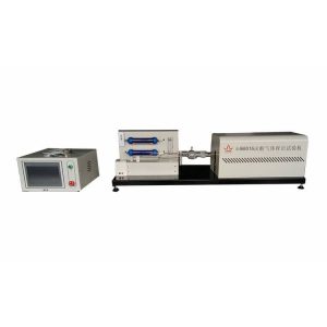
- Heat source
- Heat: Heat is provided by a pipe type gas burner, which can supply methane. Its length is 610mm and fire is dense.
- Temperature measurement: An armoured thermometer is placed near the air inlet, whose diameter is 2mm. It’s parallel to the burner and 75mm up it.
- Test fire temperature and Time (Refer to BS 6387 burning level)
A 650℃±40℃ -3H
B 750℃±40℃ -3H
C 950℃±40℃-3H
S 950℃±40℃-20Min
- Sample: Sample is one section from the finished product, more than 1200mm. Get rid of 100mm sheath and covering layer of both ends. Wires of both ends should be connected according to the electrical connections.
- Test voltage: 100-1000V, adjustable.
- Test current: 100-260mA, adjustable.
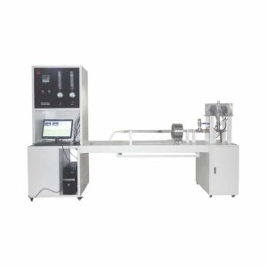
Water and fire resistance Test: W, Includes below
- Cable supporting system: Cable is connected to the metal support which is consisted of 2 steel plates, width of 25mm. Support is fixed by metal clips, distance of 200mm. ATTENTION: Metal rings and other metal parts should be earthing. Cable connects to the support.
- Continuous detection device
Let current go through all the cores of cable when in test, three single phase transformers, and has enough ability to keep max allowable leakage current of 3A under test voltage. Each core of cable in the other end connects with a lamp, and load current of 0.25A under rated voltage.
- Heat source
- Heat: A strip burner length of 500mm. It can be adjusted and can provide bright flame. Temperature: 950℃±40℃.
- Temperature measurement: One pcs of 2mm diameter thermometer is placed on the lower surface of the cable.
- Test flame temperature: 650℃±40℃.
- Water spray: A spray noozle is installed on the test support, just middle of the burner. Water pressures: 250-350KPa. Spray water 0.25-0.30L/m² around sample. This spraying rate needs to use collection tray to measure. This tray has enough depth, to let its long axis parallel to the axis of the cable and in the middle place. It’s about 100mm in width, 400 in length.
- Sample: Sample is one section from the finished product, more than 1500mm. It must have been done the bending test in environmental temperature. Get rid of 100mm sheath and covering layer of both ends. Wires of both ends should be connected according to the electrical connections.
- Test voltage: 200-1000V, adjustable.
- Test current: 100-260mA, adjustable.
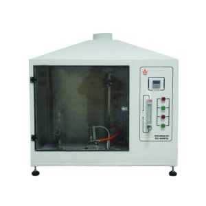
Mechanical shock and fire resistance Test, Includes below
- Cable is fixed on a vertical wall, with a heat resistance non-combustible material, fixed on two horizontal steel plates. One is upper of the plate, and the other bottom of the plate. This plate is about 900mm in length, 300mm in width, 9mm in thickness, and total weight of the wall (plate + support) is about 10 ± 2 kg. Each steel girder is square steel tube of 1m in length. If need filling materials, then need to put them inside the steel girders. Customers must fix the upper steel girder to the plate, to make its upper surface and plate’s upper surface parallel and level. There’s a horizontal hole of each steel girder and plate’s outer edge, its accurate position should be decided by specific support gasket and support framework requirements. The wall is bond to the framework by 4 rubber bushings. Bushing of diameter about 32mm, thickness about 20mm.
- Transformer is connected to fuse and lamp, used to indicate that circuit is constant
Let current go through all the cores of cable when in test, three single phase transformers, and has enough ability to keep max allowable leakage current of 3A under test voltage. Each core of cable in the other end connects with a lamp, and load current of 0.25A under rated voltage.
- Heat source
- Heat: A strip burner length of 500mm. It can be adjusted and can provide bright flame. Temperature: 950℃±40℃.
- Temperature measurement: An armoured thermometer, diameter of 2mm. It through the wall about 8-10mm. Temperature is measured by below procedure: Attach a thermometer of one end of the low carbon steel rod, to make it measure rod’s temperature. Catch this rod to the flame, keep the distance of 40-50mm. When the flame temperature is 950°C, steel rod’s temperature can reach 400°C in 10-20s; when flame temperature is 650°C, steel rod’s temperature can reach 400°C in 20-40s.
- Test flame temperature and time: Choose from below
X 650±40℃
Y 750±40℃
Z 950±40℃
- Shock device: It’s a low carbon steel rod, diameter of 25mm± 5%, length of 600mm± 5%. Its vertical section is parallel to the wall, over the top of wall 200mm. An axis divides it into two parts of 200mm and 400mm. The longer part towards the wall. Apart 30±2s, drop to the middle of the wall from the parallel position since 60°C.
- Test voltage: 200-1000V, adjustable.
- Test current: 100-260mA, adjustable.
- Ejector device: One 6.3 mm hose nozzle is included as specified in BS EN 60529:1992. Install a vertical distance (500 ± 25) mm above the specimen (45 ± 5) ° from the influence of equipment and safety, the impact of the injector equipment impact test sample points should be provided with a flow of water at 12.5 l / min By opening/closing the valve. The method of measuring the volume flow is adjusted before the test and the water supply is adjusted as necessary. An on-line flow meter should be installed in the water supply line so that the water flow rate can be monitored during the test.
- Test wall: It is used to verify the heat source and consists of non-metallic heat-resistant and non-combustible materials. The board should be long (900 ± 100) mm, high (300 ± 50) mm, thick (10 ± 2) mm, should be equipped with thermocouples to measure the flame temperature of the heat source, two diameters of 1.5 mm, mineral insulation, stainless steel armor Thermocouple, type K conforms to BS EN 60584–1.
- Timer: Measured in seconds to measure the test time and the effect of the timing device on the sample.
- Metal bolts and clips: Fixed specimen test ladder, including two u-bolts, p-type clip made of metal strips wide (20 ± 2) mm for test specimen diameter 50 mm wide (30 ± 3) mm, using specimens over diameter 50 Millimeter. All clips and bolts should be grounded.
- The instrument uses computer software to control and monitor the current, voltage and gas flow during the test. The test result curve can be output and printed.
Specification:
- Dimension:
- Fire resistance and impact: 2430*770*1600 mm
- Control cabinet: 800*800*2000 mm
- Water tank: 1500*1200*900 mm
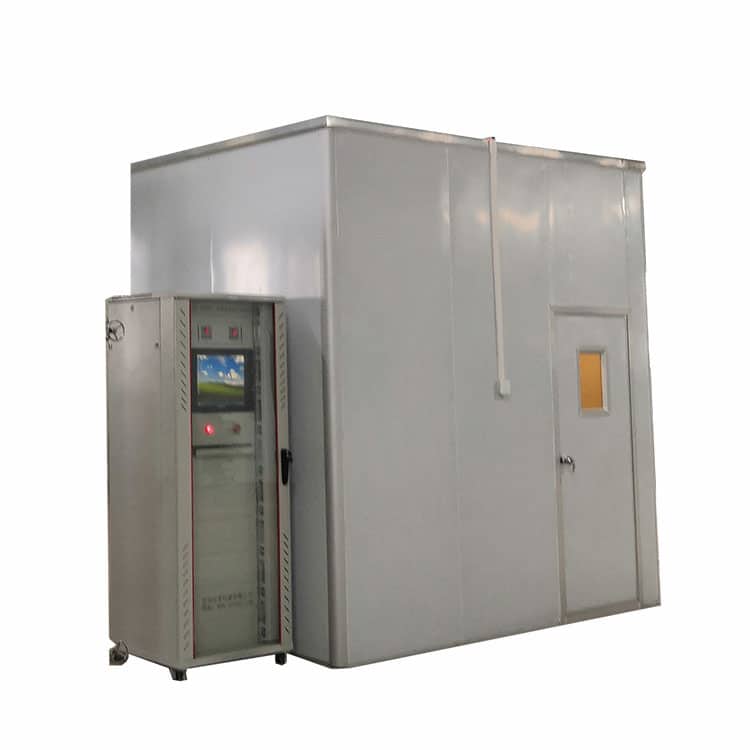
- Burning chamber: 3*3*3m (Optional)
- Gas source: Propane, air (Customers-owned)
- Power: 3 PH 5 lines: AC380V+N, 50/60Hz, 32A